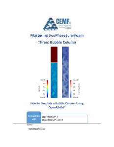
You will learn how to simulate a bubble column suing OpenFAOM®. All the details on sub-models and simulation settings are presented in this tutorial. You can also see the animation of the simulation results here.
- Solver: twoPhaseEulerFoam
- Compatible with: OpenFOAM 7, OpenFOAM 6, OpenFOAM v1912
- Model: Euler-Euler compressible flow, RAS turbulence model, 2D & 3D
- Physical System: A bubble column with air and water is simulated.
- Description: The bubble column (see here for technical details) in this tutorial is a cylinder with internal diameter of 0.26 m and height of 2 m. One meter of the column is initially filled with water at 300 K and atmospheric pressure. Air (at 300 K) enters from the bottom of the column through a perforated distributor (here, a uniform gas is assumed for simplicity). This simulation is performed based on the experiments of Kumar et al. [Kumar, Moslemian, and Dudukovic, 1997. AIChE Journal, 43, 1414-1425] with some slight changes.


Saludos profe Norouzi,
Tengo una consulta, este solver lo implemente en un reactor de flotación con agua y un ingreso de aire por la parte inferior del reactor y funciona, ahora si yo quisiera hacer esto añadiendo un polímero para aglutinar solidos suspendidos y que se haga mas eficiente su eliminación con ingreso de aire en el agua, para ese proceso complejo que solver seria adecuado? Gracias desde ya por su respuesta
I dont know Spanish. So please let me know about your question in English.
Greetings Prof Norouzi.
I have a query, I implemented this solver in a flotation reactor with water and an air inlet through the bottom of the reactor and it works, now if I wanted to do this by adding a polymer to bind suspended solids and make their elimination more efficient by flotation, for that complex process which solver would be suitable
I am not aware of any solver that can directly solve this specific problem. But you may need addition of some sub-models (by C++ programing) and use them with standard solvers (like twoPhaseEulerFoam). To give u a hint, you may want to consider the effect of polymer on your particle in the form of some hydrodynamic forces that act on solid particles. this would be straight-forward. Any approach for modeling this process, requires it own solution.
It seems very diffcult, but I will try.
Thank you so much.
Greetings Prof Norouzi,
Thank you for this high quality tutorial! I learned a lot about twoPhaseEulerFoam solver. It provides lots of useful information.
When I read these files and the related paper, I have some questions:
First, what are differences between granule temperature (theta) and T.particles?
Second, what is alphat? I saw two alphat files in 0 folder.
Thank you!
Welcome. theta is granular temperature, which is used in the Kinetic theory of granular flow model, a model that describes the rheological behavior of granular matter as a continuous fluid. T.particles is the actual temperature of particles that comes from the energy equation (energy balance) of the solid phase.
Alphat is a field that is meaningful if turbulent flow of fluids like gas and liquids (turbulent thermal diffusivity of the fluid, here particle phase). It has no use in the KTGF, but since the kinetic theory (KTGF) is build up on the basic classes of turbulent flow (from programing point of view in C++), this field is required to be in time folder by default.
Greetings Prof Norouzi,
I would like to simulate an isothermal bubbly flow (air-water) using OpenFOAM. Is twoPhaseEulerFoam the right solver for it? If yes, is there a way to make it isothermal?
Many Thanks in advance
Yes, it is the right solver for it (for versions 7 and bellow).
Just use similar temperatures for both phases and inlets. And use isothermal diameter model for the bubbles (bubble diameter changes with pressure only). It will be isothermal.
Hint: if the temperatures of the gas phase and the liquid phase are set a bit different (i.e. 0.5 deg C), the energy equation solver converges better and still you have isothermal solution.
Hello Prof. Norouzi,
Could you please give more explanation on the air volume fraction in inlet. Why the air volume fraction in inlet need to equal to 0.5 ? Despite the superficial velocity (q=0.05m/s), could the air volume fraction in inlet (alpha.air) = 1 and U.air = 0.05 instead ?
Is there any limitation on why alpha.air cannot equal to 1 at the inlet ?
Hi, this value indicates that half of the inlet surface area is covered by liquid. Do we have any evidence of such an assumption? No. Important thing here is the inlet mass flow rate.
You can use alpha.air = 1 at the inlet, then you must set the inlet velocity to 0.025 m/s to get the same mass flowrate of air in the inlet (mass flowrate = rho*alpha*U*S).
My experience: I sometimes use values near 1 (i.e. 0.9999) and near zero (0.0001) for the patches. This setup, in some cases, makes the solver stable, specially when there is high velocity in the inlets and outlets and/or complex thermodynamic (multicomponent phase) in the simulation (true for lower versions like OF7 and OF1912). Recently they revised the solver, and I rarely see such problems.
Thank you Professor Norouzi for the clarification and valuable information.